Putting the pistons back in the SP&S 700
All photos by Terry Thompson.
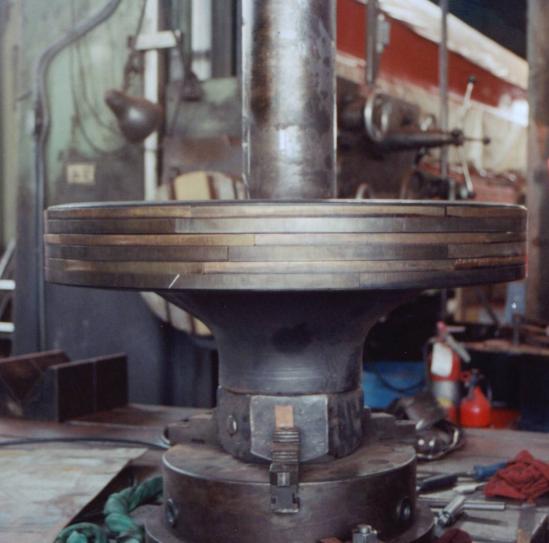
This shows how the segmented rings appear when in the piston (but without the expander spring - otherwise the rings would go flying).
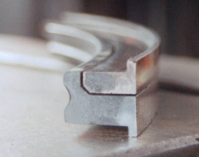
There are two kinds of rings, a bronze "L" ring and a cast iron "Z" ring that fit together in the ring land.
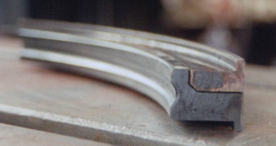
This view shows the inner groove for the ring expander spring.
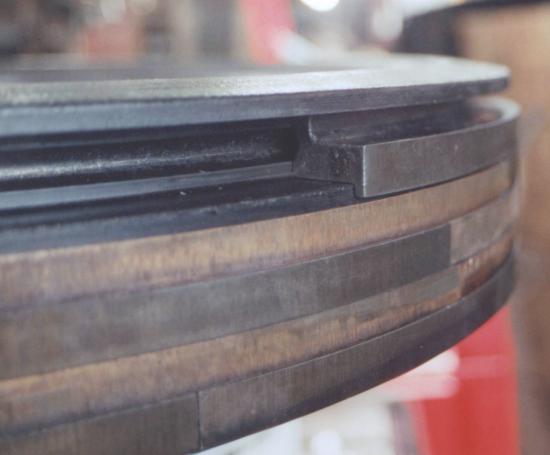
This view shows a "Z" ring as it would fit. Note the semicircular groove in the land matching the groove in the "Z" ring. The resulting circular hole is where the ring expander spring resides.
The above photos were taken earlier this summer. The shots below were taken in early Sept when the pistons were going back in the loco.
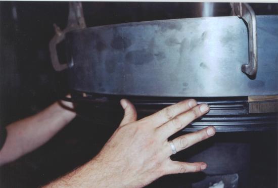
For each groove, we slip the temporary retainer down to hold in the rings while the expander spring is put into place. Tom Weisner's right hand thumb and index finger are guiding the spring while his left hand is pushing the spring into place.
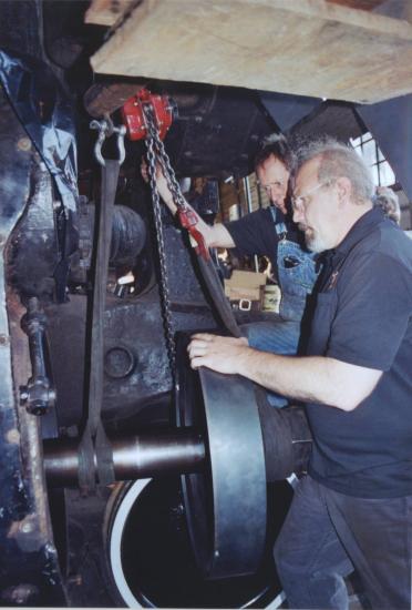
Jim Vanderbeck and Tom Weisner slide the piston into the cylinder.
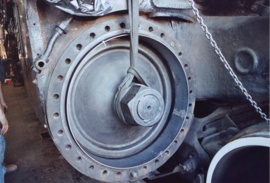
The piston has been pushed into the cylinder leaving the temporary retainer behind. At its entrance, the cylinder has a tapered shoulder (called the ring compressor) to squeeze the rings against the expander spring, so the temporary retainer goes in as far as the ring compressor and stops there.